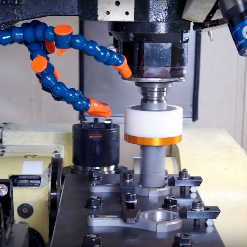
Setting up your tooling
All CNC tooling should be treated as a precision product. Extra care should be taken not to damage tapers, connecting surfaces or introduce contaminating dirt onto connection surfaces.
Presetting Requirements
| Required | Consider | Notes |
|---|---|---|
| Required PPE | Gloves Eye protection Ear plugs Protective footware |
|
| Presetter | ||
| Correct spindle adaptor | Adaptors can change the usable length of a presetterEnsure that the presetter is long enough with the correct adaptor | |
| Tool drawings | RADS printout contains all the required information to set the tool | |
| Inserts | Size, grade, geometry, nose radius | |
| Pull Studs | Details of the correct pull stud can be found on the machine tool | |
| Coolant Tubes | Some shanks like HSK require separate coolant tubes – Failure to fit can damage spindle seals | |
| Balluff Chips | Tool ID chips used for storing unique | |
| Adjusting Tools | ||
| Blue Tack | Used for cleaning cutting edges when using non-contact measurement to preset tooling | |
| Engineering Blue |
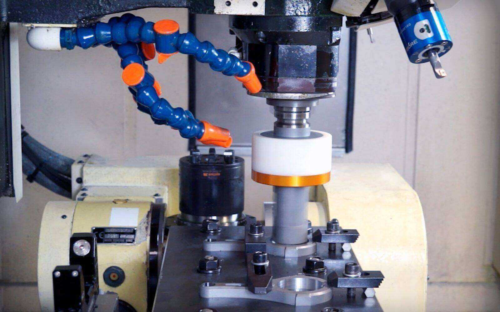
Setting up tooling
All CNC tooling should be treated as a precision product. Extra care should be taken not to damage tapers, connecting surfaces or introduce contaminating dirt onto connection surfaces.
Rigibore tools are preset before shipping with gauge inserts. However, you will need to fit inserts and adjust preset dimensions prior to first use.
| Action | Notes |
|---|---|
| Setup presetter | |
| Clean all connecting adaptor faces and assemble presetter components | |
| Calibrate presetter | Calibration hardware/software supplied by the presetter manufacturer |
| Unpack the tool | Required adjustment tools may be fastened to the outside of the packaging |
| Keep any reusable packaging for future storage of the tooling | |
| Fit required pull stud or coolant tube | Correct torques must be applied to pull studs, over tightening can deform tapers causing performance problems or damaging spindles |
| Clean the tool taper and insert into presetter adaptor | Ensure the correct adaptor program is selected on the presetter |
| Clamp tool into presetter ensuring for good connection | |
| Starting with the tool furthest from the taper carefully remove the insert screw with the correct torx key and fit the insert to the pocket | Ensure correct radius of insert |
| Visually inspect for good seating | Ensure there are no gaps between the pocket and the insert base. If unsure use a piece of shim to check for any clearances, if you cannot seat the insert, check for debris in the pocket or on the base of the insert, clean and repeat check |
| Tighten the insert screw | Ensure for an element of pull back roughly 1/4 turn on the insert screw |
| Clean cutting edge using blue tack | This removes any contamination that may affect non contact measurement systems on most modern presetters |
| Using the presetter, measure the position of the cutting edge and course adjust | Make course adjustment > ±0.1mm, if required, to length first then the diameter |
| Repeat items 13.0 to 13.5 until rough setting is complete on all edges of tool | |
| Establish critical component or reference dimensions for tooling | Combination tools may contain a number of cutting edges, some of these edges may have critical relationships such as two blind holes. Other features may be relative but not critical to these features, for example a chamfer |
| Starting with the critical or reference edge, adjust to finish size. Continue to adjust all edges to finish size | |
| Make a note of all edge positions and note and double check tool offset dimensions required for the machine | |
| Clearly label tool as set |
Run-off requirments
The most important part of this phase is the planning and pre assessment of the expected results.
As with all machining processes the entire process must be monitored and controlled to achieve tight tolerances and good process stability or a high CPK.
Besides the tooling there are many factors that impact the performance of hole boring processes.
| Criteria | Details | Notes |
|---|---|---|
| Material variation | Material variance has a huge impact on boring bars | Hardness, inclusions, chemical composition |
| Core shift | For boring processes the start process is usually a pre-formed hole. This may be pre-cast or pre-forged or it may be pre-drilled | |
| Fixture/component positioning | ||
| Fixture/component clamping forces | ||
| Program datum positioning | ||
| Coolant supply | ||
| Required PPE | Safety glasses Safety shoes Ear protection Gloves |
|
| Machine tool access | Access to a guarded machine tool with all required safety features fitted including interlocks and guards | |
| Parts | Access to test parts | |
| Programs | Pre written programs, verified with correct offset requirements, required spindle orientations and clearance distances | |
| Offsets | Tool length offset measurements | |
| Measurement equipment | Manual methods of measuring tool cutting results | |
| Start point speeds and feeds | Estimated speeds and feeds for the tool based on standard industry prerequisites | See specific section on speeds and feeds |
For more information, see also